-
 [email protected]
-
 +86-13605711675
[email protected]
+86-13605711675


Model range: NRV 025/030/040/050/063/075/090/110/130
Transmission ratio: 5:1 to 100:1 (multiple stages in series can achieve higher ratios)
Input power: 0.12 kW ~ 22 kW (depending on the model)
Output torque: 15 N·m ~ 3000 N·m
Input speed: Recommended ≤ 1500 r/min (some models support 1800 r/min)
Mounting form: Flange (B5/B14), base (B6/B7) or vertical installation
Efficiency: Single-stage efficiency 70%~92% (decreases with increasing transmission ratio)
Weight: 2 kg ~ 200 kg (depending on the model and material)
Protection level: IP65 (standard), IP66 (enhanced sealing)
Operating temperature: -20℃ ~ +90℃ (short-term tolerance up to 120℃, high temperature grease is required)
NRV series worm gear reducer is a right-angle reduction device based on worm gear transmission.
Its core features include:
- Structural design: 90° right-angle output, saving installation space and adapting to complex mechanical layout.
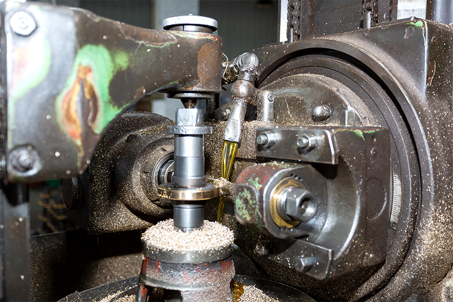
- Material combination: The worm is made of high-strength alloy steel (such as 20CrMnTi), the worm wheel is wear-resistant bronze (CuSn12 or CuSn6Zn6Pb3), and the housing is die-cast aluminum alloy (ADC12).
- Self-locking function: It has self-locking ability when the transmission ratio is ≥ 30:1 to prevent load reversal.
- Modular expansion: It supports multi-stage series or parallel connection to flexibly match different power requirements.
Industrial Automation: Robotic arm joints, conveyor belt drives, automated assembly lines
Food Processing: Mixers, filling machines, packaging line power transmission (food-grade grease required)
Construction Machinery: Small cranes, roller shutter door drives, ventilation systems
New Energy Equipment: Solar tracking brackets, wind power generation pitch systems
Medical Equipment: Operating table adjustment, imaging equipment rotation mechanism|
1. High-efficiency transmission
- Optimized worm gear meshing surface, with efficiency up to 92%, and energy consumption reduced by 15%~20%.
2. High load-bearing capacity
- The worm is carburized and quenched (hardness HRC58-62), and the worm wheel adopts centrifugal casting process, which improves wear resistance by 50%.
3. Low-noise operation
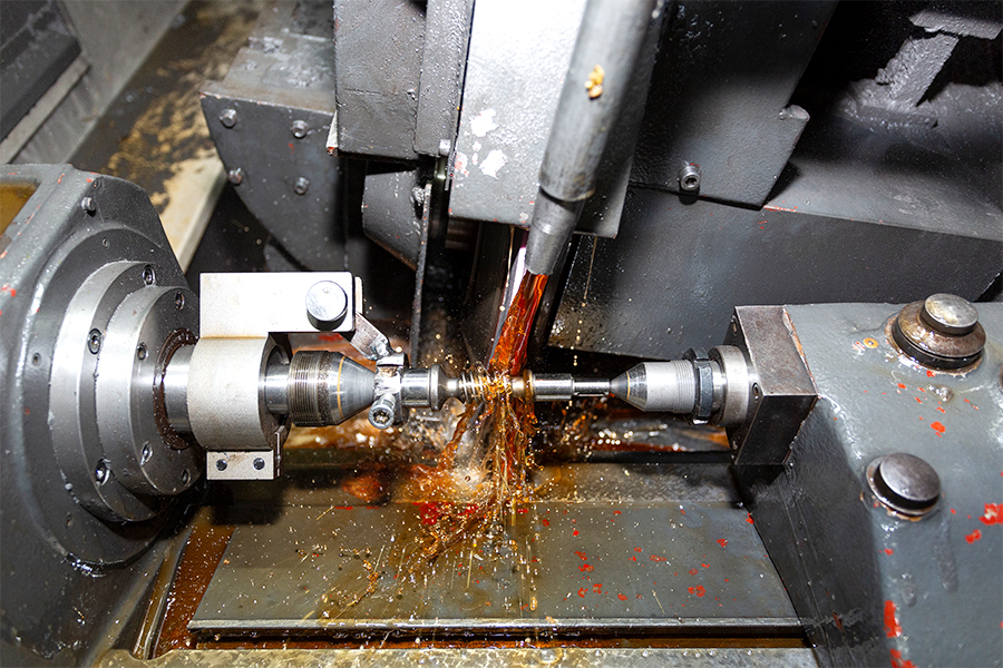
- Precision gear grinding process (tooth surface roughness Ra≤0.8μm), operating noise ≤68 dB(A).
4. Reliable sealing
- Double lip oil seal + labyrinth seal structure to prevent lubrication leakage and contaminant intrusion.
5. Easy maintenance
- Split housing design, the worm wheel can be replaced or the clearance can be adjusted without disassembling the whole machine.
6. Intelligent adaptation
- Optional encoder and brake modules are available to support servo motor closed-loop control.
The technical process of worm gear reducer integrates the three core advantages of high-strength materials, precision processing, and modular design. Through carburizing and quenching, CNC gear grinding, double seal structure and other innovative processes, it achieves a balance between high precision, high reliability and environmental adaptability. Its process cost is relatively high, but it is suitable for industrial scenarios with strict performance requirements, such as automation, new energy and medical equipment.
For exclusive deals and latest offers, sign up by entering your email address below.
In modern mechanical and industrial systems, efficient power transmission is essential for reducing energy consumption and ensuring stable operation. Among various transmission solutions, NMRV NRV warm gearboxes have become widely recognized for their compact structure, reliable ...
View MoreWorm gearboxes transmission systems are widely used in industrial machinery, conveyor systems, lifts, and automation equipment due to their compact design, high reduction ratios, and quiet operation. However, like any mechanical power transmission device, they are prone to specif...
View MoreIn the world of mechanical power transmission, few devices offer the same combination of simplicity, compactness, and torque multiplication as a worm gear speed reducer. Whether you are an engineering student, a maintenance technician, or a hobbyist building your first automated ...
View More1. The core challenges of heavy load conditions for reducers
High torque and impact load: Instantaneous load characteristics in mining, metallurgy, port machinery and other scenarios.
Continuous operation heating problem: The impact of temperature rise caused by worm gear friction on lubrication and materials.
Wear and fatigue life: Common failure modes such as tooth surface wear and bearing failure.
2. Energy efficiency optimization design of NRV worm gear speed reducers
High-precision worm process: Gear grinding technology is used to reduce friction loss and improve transmission efficiency (up to more than 90%).
Special lubrication solution: High-temperature synthetic lubricant or grease lubrication to reduce thermal attenuation.
Lightweight and heat dissipation structure: Box heat dissipation fin design or forced cooling option.
3. Key technologies for enhanced durability
Material selection: The worm is hardened with alloy steel, and the worm wheel uses wear-resistant tin bronze (ZCuSn10Pb1).
Sealing and corrosion protection: IP65 protection level and special coating for humid or dusty environments.
Load test data: Comparison of MTBF (mean time between failures) cases under standard working conditions and heavy loads.
4. Industry application cases
Cement industry: Long-term stability of raw mill drive system.
Lifting equipment: Reliability verification under frequent start-stop and variable load conditions.
Steel rolling mill: Anti-fatigue performance in high temperature environment.
5. Maintenance recommendations and energy efficiency trade-offs
Regular inspection points: oil contamination, tooth surface wear marks.
Balance between energy efficiency and cost: initial investment vs. long-term energy saving benefits (such as comparison with gear reducers).
Maintenance and troubleshooting: key practices to extend the service life of NRV worm gear reducers
1. Key points of daily maintenance
Lubrication management
Regularly check the oil level and oil quality (contamination, oxidation, water mixing).
Select the appropriate lubricant (mineral oil, synthetic oil or grease) according to the working conditions. High temperature resistant grease should be used in high temperature environments.
Change the oil after the first 500 hours of operation, and then change it every 4000-5000 hours or annually (depending on the working conditions).
Tightening and sealing inspection
Check whether the bolts and flange connections are loose to prevent structural damage caused by vibration.
Replace seals (such as oil seals and O-rings) in time when they are aged or leaking to avoid dust/water intrusion.
Temperature and vibration monitoring
Use infrared thermometers to monitor bearing and worm temperatures (abnormal temperature rise may indicate insufficient lubrication or overload).
Vibration analyzers detect abnormal vibrations (which may be caused by shaft misalignment, gear wear or bearing damage).
2. Common failure modes and troubleshooting methods
(1) Abnormal noise
Possible causes: insufficient lubrication, gear wear, bearing damage, loose assembly.
Troubleshooting steps:
Check whether the lubricating oil is sufficient or contaminated, and replace it if necessary.
Disassemble and inspect the worm gear tooth surface to observe whether there is peeling or pitting.
Manually rotate the bearing to confirm whether there is any sticking or abnormal noise, and replace it if necessary.
Check whether the connecting bolts are loose and re-tighten them.
(2) Oil leakage
Possible causes: aging of seals, cracks in the housing, improper installation of oil seals, and excessive oil level.
Troubleshooting steps:
Check whether the oil seals, O-rings and other seals are hardened or damaged, and replace the failed parts.
Observe whether the housing has cracks or sand holes, and repair or replace the housing if necessary.
Confirm whether the oil level exceeds the upper limit of the calibration and adjust it to a reasonable range.
(3) The output shaft is stuck or rotates poorly
Possible causes: excessive load, bearing damage, foreign matter entering the housing, and shaft misalignment.
Troubleshooting steps:
Check whether the load exceeds the rated value and adjust the equipment operating parameters.
Disassemble and check whether the bearing is damaged and replace the faulty bearing.
Clean up metal debris or other impurities in the box.
Recalibrate the shaft alignment of the motor and the reducer (laser alignment instrument is preferred).
(4) Significant decrease in efficiency (too high temperature rise)
Possible causes: excessive wear of the worm gear, poor lubrication, insufficient heat dissipation, overload operation.
Troubleshooting steps:
Check the wear of the tooth surface. If the wear exceeds 10%, the worm gear pair needs to be replaced.
Replace the lubricating oil that meets the standards and ensure that the oil circuit is unobstructed.
Clean the heat sink or install a forced cooling device (such as a fan).
Check whether the actual load matches the rated power of the reducer.
(5) Abnormal vibration
Possible causes: shaft misalignment, loose anchor bolts, poor gear meshing, and bearing wear.
Troubleshooting steps:
Use a dial indicator or a laser alignment instrument to correct the coaxiality of the input/output shaft.
Tighten the anchor bolts and check whether the shock pads are aged.
Check the meshing clearance of the worm gear and adjust it to the standard range.
Replace damaged bearings or gear parts.
3. Life management of key components
Worm gear pair: Regularly check the pitting and peeling of the tooth surface. Replace when the wear exceeds 10% of the tooth thickness.
Bearings: It is recommended to replace every 20,000-30,000 operating hours or when abnormal noise occurs.
Oil seals: Replace every 1-2 years, and the cycle is shortened in dusty/humid environments.
4. Example of preventive maintenance plan
Daily: Check the oil level, abnormal noise and leakage.
Monthly: Tighten the bolts and clean the external heat dissipation structure.
Every six months: Oil test (viscosity, acid value, particulate matter).
Yearly: Comprehensive disassembly and inspection, replace wearing parts (such as seals, filters).
5. Advanced practice to extend life
Load optimization: Avoid long-term overload operation and use inverters to reduce startup shock.
Environmental control: add protective covers (dust and moisture proof), and add cooling fans in high temperature environments.
Data-driven maintenance: integrate IoT sensors (temperature, vibration, oil quality) to achieve predictive maintenance.