-
 [email protected]
-
 +86-13605711675
[email protected]
+86-13605711675


1. Model example: NMRV-VS 25/30/40/50/63/75/90/110
2. Transmission ratio range: 7.5~100 (common models)
3. Input power: 0.06kW~15kW (depending on the model)
4. Output torque: 10N·m~2000N·m
5. Input speed: ≤1500r/min (recommended)
6. Installation form: flange type (B5/B14) or base type (B6/B7)
7. Efficiency: 70%~90% (adjusted according to transmission ratio and load)
8. Weight: 1.5kg~120kg (varies greatly between different models)
9. Protection level: IP65 (dustproof and waterproof)
10. Operating temperature: -20℃~+80℃
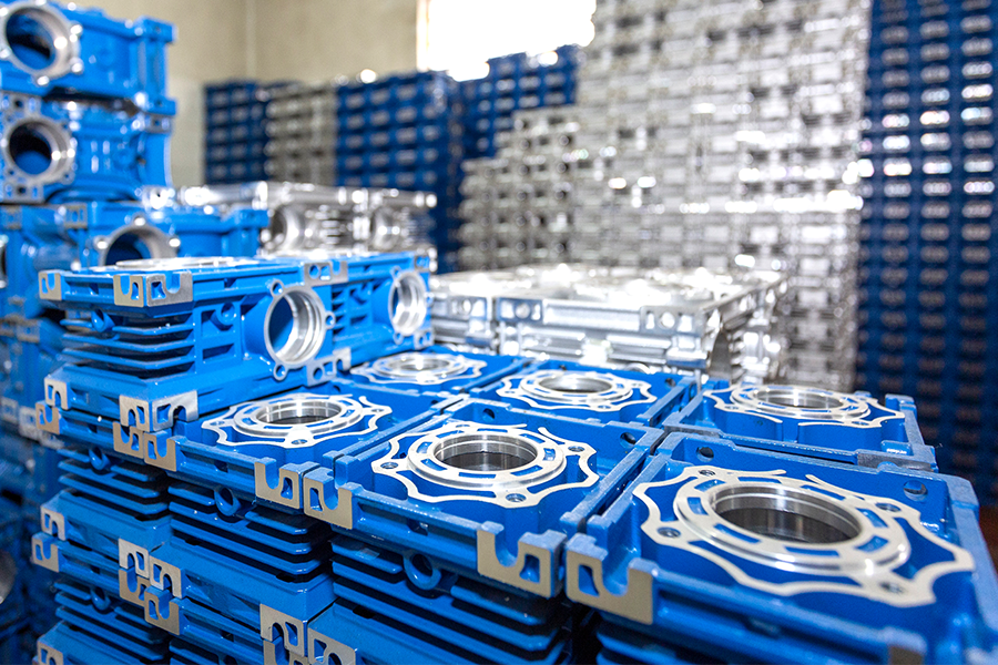
NMRV-VS worm gear reducer is a high-efficiency reduction device based on the principle of worm gear transmission. It adopts an aluminum alloy housing and a precision copper worm gear. It has a compact structure, high load-bearing capacity and low noise.
Its core features include:
- Worm gear structure: The worm (input shaft) and the worm wheel (output shaft) are driven at a 90° right angle to achieve space layout optimization.
- Self-locking function: It has reverse self-locking characteristics under a specific transmission ratio to prevent load reversal.
- Modular design: It can be directly connected with a variety of motors (such as servo motors, stepper motors) with strong adaptability.
- Material technology: The housing is made of high-strength aluminum alloy, and the worm wheel is wear-resistant phosphor bronze to extend the service life.
Food machinery: mixers, filling machines, conveyor belt drives.
- Packaging equipment: sealing machines, labeling machines, automatic packaging lines.
- Logistics systems: sorting machines, lifting platforms, roller conveyors.
- Medical equipment: operating table adjustment, laboratory instrument transmission.
- Construction machinery: small cranes, roller shutter door drives, ventilation equipment.
1. Compact and lightweight
- The aluminum alloy housing reduces weight and is easy to integrate into space-constrained equipment.
2. Efficient transmission
- The optimized design of worm gear meshing reduces energy loss and improves transmission efficiency.
3. High load-bearing and durability
- The copper worm gear is hardened and has strong wear resistance, suitable for frequent start-stop conditions.
4. Low-noise operation
- Precision machining ensures smooth meshing, noise ≤65dB (A), suitable for quiet environments.
5. Flexible installation
- Supports multi-angle installation (flange or base), suitable for different motor interfaces.
6. Maintenance-free design
- High-performance grease is pre-filled at the factory, and the sealing structure extends the maintenance cycle (it is recommended to check every 8,000 hours).
7. Safe and reliable
- The self-locking function prevents the load from accidentally sliding down, suitable for vertical lifting scenarios.
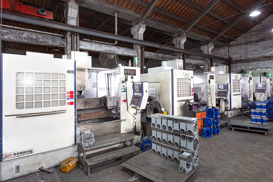
The technical process of worm gear reducer integrates the three core advantages of high-strength materials, precision processing, and modular design. Through carburizing and quenching, CNC gear grinding, double seal structure and other innovative processes, it achieves a balance between high precision, high reliability and environmental adaptability. Its process cost is relatively high, but it is suitable for industrial scenarios with strict performance requirements, such as automation, new energy and medical equipment.
For exclusive deals and latest offers, sign up by entering your email address below.
In modern mechanical and industrial systems, efficient power transmission is essential for reducing energy consumption and ensuring stable operation. Among various transmission solutions, NMRV NRV warm gearboxes have become widely recognized for their compact structure, reliable ...
View MoreWorm gearboxes transmission systems are widely used in industrial machinery, conveyor systems, lifts, and automation equipment due to their compact design, high reduction ratios, and quiet operation. However, like any mechanical power transmission device, they are prone to specif...
View MoreIn the world of mechanical power transmission, few devices offer the same combination of simplicity, compactness, and torque multiplication as a worm gear speed reducer. Whether you are an engineering student, a maintenance technician, or a hobbyist building your first automated ...
View More1. The core significance and technical background of meshing clearance control
In the field of mechanical transmission, the meshing clearance of worm gears (also known as side clearance) is a key parameter that affects transmission accuracy, noise level and service life. Taking the NMRV-VS worm gear speed reducer produced by Hangzhou Yinhang Reduction Gears Co., Ltd as an example, its application scenarios cover high-precision fields such as chemical industry, new energy, and robots, so the control of meshing clearance needs to reach the micron level standard. Too small a clearance can easily lead to friction heating, increased wear, and even jamming; too large a clearance can cause transmission idle travel, impact vibration, and excessive noise (such as exceeding the standard of 65dB (A)). With more than 15 years of industry experience, the company has formed a gap control system that integrates precision machining, dynamic detection, and modular assembly based on material selection (alloy steel worm, hardened copper worm wheel) and process design (aluminum alloy lightweight housing).
2. Precision control of core components before assembly
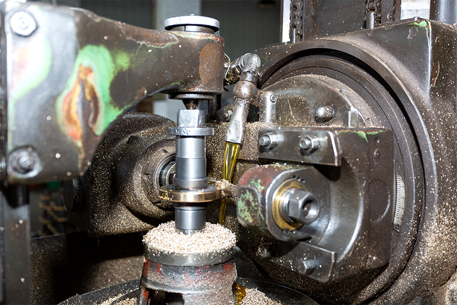
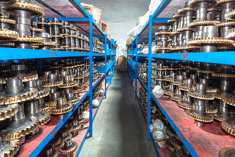
(1)Material and processing precision basis of worm and worm wheel
The NMRV-VS series uses 20CrMnTi carburized and quenched worm with a surface hardness of HRC58-62. The tooth surface is processed by CNC grinding process, and the tooth shape error is ≤0.012mm and the tooth direction error is ≤0.015mm. The worm wheel is made of ZCuSn10Pb1 tin bronze, which is formed by centrifugal casting process and then aging treatment to eliminate internal stress. The tooth surface roughness Ra≤1.6μm. The test laboratory will perform three-coordinate detection on each batch of parts to ensure that the cumulative error of the worm pitch is ≤0.02mm and the radial runout of the worm gear ring is ≤0.03mm, so as to control the influence of the geometric accuracy of the parts on the clearance from the source.
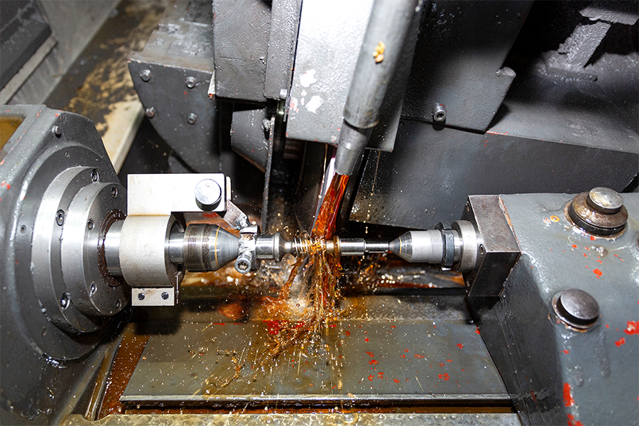
(2)Design of matching precision of the housing and the bearing position
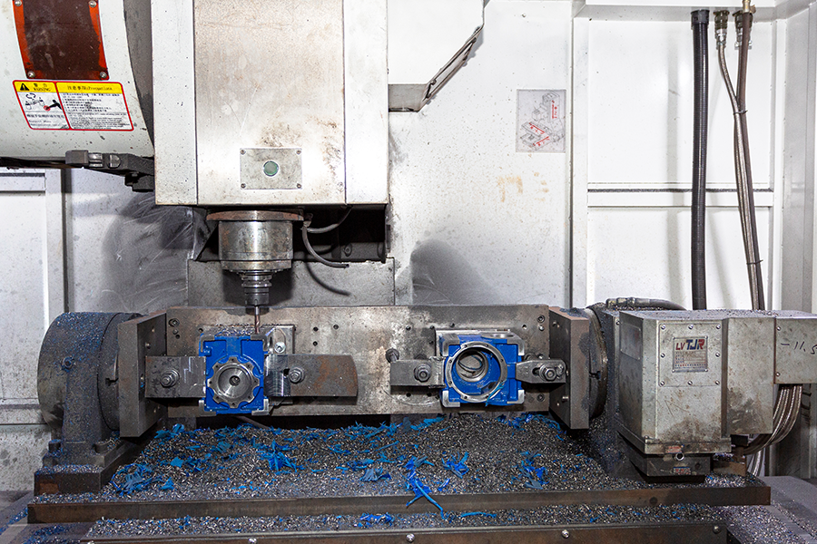
After the aluminum alloy housing is die-cast, the bearing mounting hole is fine-bored, and the hole tolerance is controlled at H7 level and the surface roughness Ra≤3.2μm. The coaxiality error of the bearing position is ≤0.02mm, and the verticality error is ≤0.015mm to ensure the spatial position accuracy of the worm and worm wheel axis. For example, if the coaxiality deviation of the front and rear bearing holes of the box exceeds 0.03mm, it will cause partial load during meshing and cause uneven clearance. Therefore, the constant temperature processing environment of the CNC machining center (temperature controlled at 20±1℃) is used to ensure the accuracy of the box.
3. Quantitative control process of clearance during assembly
(1)Classification and dynamic measurement of clearance standards
According to the transmission ratio (i=5-100) and load conditions, the NMRV-VS series divides the meshing clearance into three levels: light load precision level (0.05-0.10mm), medium load general level (0.10-0.15mm), and heavy load impact resistance level (0.15-0.20mm). During assembly, the "lead pressing method" or "dial gauge measurement method" is used for real-time detection:
Lead pressing method: 3-5 lead wires with a diameter of 0.1-0.3mm are evenly placed on the worm gear tooth surface, and the worm wheel is rotated manually. The thickness difference after the lead wire is squeezed is the actual clearance.
Dial gauge measurement method: Place the dial gauge head against the worm gear tooth surface, fix the worm and reciprocate the worm gear. The difference in the swing of the dial gauge needle is the clearance value. The assembly process document requires that each meshing position be tested at least 3 times, and the average value is taken as the basis for adjustment.
(2)Core technical means for clearance adjustment
Preload control of bearing clearance
When using tapered roller bearings or angular contact ball bearings, adjust the thickness of the gasket at the end cover (accuracy 0.01mm level) to preload the bearing to eliminate the influence of axial clearance on the clearance. For example, when the clearance is detected to be too small, the thickness of the bearing end cover gasket is increased (such as 0.05mm) to cause the worm to move axially and increase the meshing clearance; otherwise, the thickness of the gasket is reduced. The modular design allows precise fine-tuning of the clearance by replacing adjustment gaskets of different thicknesses (standard parts inventory covers 0.05-0.5mm specifications).
Dynamic calibration of the axial position of the worm gear
The worm gear is installed through the interference fit between the hub and the shaft. During assembly, a special tool is used for positioning to ensure that the perpendicularity between the symmetry plane of the worm gear and the axis of the worm gear is ≤0.02mm. If the clearance is uneven (such as 0.1mm on one side and 0.15mm on the other side), the worm gear needs to be disassembled and the axial position needs to be adjusted by scraping the hub mating surface or replacing the eccentric sleeve (eccentricity 0.05-0.1mm) so that the meshing area is evenly distributed within the middle 1/2 of the tooth width. The R&D team of Hangzhou Yinhang Reduction Gears Co., Ltd has developed a digital assembly platform that simulates the effect of the worm gear installation position on the clearance through 3D modeling, and predicts the adjustment amount in advance.
Running-in and aging treatment of gear pairs
After assembly, the gear pairs need to be run-in for 2 hours at no load and 120% rated load, respectively, with a running-in speed of 100-300r/min. During the running-in process, the microscopic protrusions on the surface of the gear pair will be gradually smoothed, and the clearance may change by 0.01-0.03mm. After running-in, the clearance is checked again. If it exceeds the standard range, the bearing preload or worm gear position needs to be adjusted repeatedly. The test laboratory is equipped with a vibration spectrum analyzer to monitor noise and vibration data simultaneously during running-in to ensure that the noise is ≤65dB (A) and the vibration acceleration is ≤5m/s² after the clearance adjustment.
4. Process innovation and quality control system
(1)Synergy of double seal structure and lubrication system
The NMRV-VS series adopts a "skeleton oil seal + O-ring" double seal structure to prevent grease leakage and prevent external impurities from entering the meshing area and causing gap changes. The factory-prefilled lithium-based grease (NLGI grade 2) has a high viscosity index and can maintain a stable oil film thickness (about 2-5μm) in the temperature range of -20℃ to 120℃, assisting in compensating for small gap fluctuations. The quality control system of Hangzhou Yinhang Reduction Gears Co., Ltd will weigh and test the grease filling amount during the assembly stage to ensure that the grease amount error of each reducer is ≤±5%, avoiding abnormal wear of the gap due to insufficient lubrication.
(2)Full-process dynamic detection and traceability mechanism
From the storage of parts to the delivery of finished products, a total of 7 clearance detection processes are set up:
Single-piece precision detection of worm/worm gear;
Position detection of housing bearing hole;
Clearance detection after assembly of bearing and shaft;
Static clearance detection after initial assembly of worm gear;
Dynamic clearance re-inspection after running-in;
Clearance stability detection after load test;
Final sampling before packaging.
The detection data of each process needs to be recorded and uploaded to the MES system, and customers can trace the entire assembly process through the product QR code.
5. Technical advantages and industry practices
As a professional manufacturer in the field of reducers for 15 years, Hangzhou Yinhang Reduction Gears Co., Ltd has incorporated three core advantages into the gap control of the NMRV-VS series:
Material process advantages: The carburizing and quenching depth of the alloy steel worm reaches 0.8-1.2mm, and the uniformity deviation of the tooth surface hardness is ≤HRC2, ensuring that the gap change after long-term operation is ≤0.01mm/1000 hours;
Processing equipment advantages: The German Klingberg CNC gear grinding machine is introduced, and the worm tooth profile accuracy reaches ISO 6 level. The worm gear hobbing adopts Japanese Mori Seiki equipment, and the cumulative pitch error is ≤0.015mm;
Modular design advantages: Through the standardized bearing seat and adjustment shim design, 80% of the assembly process can be quickly completed through tooling, and the gap adjustment time of a single reducer is shortened from 2 hours in the traditional process to 45 minutes, while ensuring the consistency of mass production.
In scenarios such as new energy photovoltaic tracking systems and intelligent logistics sorting equipment, the NMRV-VS series achieves a transmission positioning accuracy of ±0.5° and a durability of ≥100,000 starts and stops with precise gap control, meeting the stringent requirements of high-end industrial scenarios for transmission stability.