-
 [email protected]
-
 +86-13605711675
[email protected]
+86-13605711675

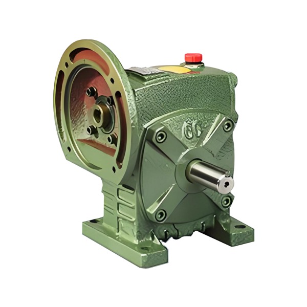
In the world of mechanical power transmission, few devices offer the same combination of simplicity, compactness, and torque multiplication as a worm gear speed reducer. Whether you are an engineering student, a maintenance technician, or a hobbyist building your first automated machine, understanding this essential component will help you make better design and procurement decisions.
A worm gear speed reducer is a mechanical device that reduces rotational speed while increasing torque. It consists of two main elements: a worm (which looks like a screw) and a worm wheel (a gear with helical teeth). The worm is the driving component; the worm wheel is the driven component.
Unlike conventional gear trains where shafts are parallel, a worm gear speed reducer typically transmits motion between perpendicular, non-intersecting shafts. This right-angle configuration saves space and allows compact machine designs.
The operating principle is deceptively simple. As the worm rotates, its helical threads push against the teeth of the worm wheel. Because the worm’s thread is essentially a continuous, inclined plane wrapped around a cylinder, each full rotation of the worm advances the worm wheel by only one tooth (or a fraction of a tooth).
This geometry creates a high reduction ratio in a single stage. For example, if the worm has a single start (one continuous thread), one full turn of the worm moves the worm wheel by one tooth. If the wheel has 50 teeth, the output shaft rotates at 1/50th of the input speed.
Key mechanical behaviors:
Important: Not all worm drives are self-locking. The self-locking condition depends on the lead angle and friction coefficient. A rule of thumb: a lead angle below about 5–6 degrees generally provides self-locking behavior.
Understanding the parts helps in troubleshooting and selection. Below is a simple breakdown:
| Component | Function |
|---|---|
| Worm (input) | A hardened steel shaft with helical threads; connects to the motor. |
| Worm wheel (output) | A bronze or brass gear that meshes with the worm; reduces speed and increases torque. |
| Housing | Encloses the gear set, holds lubricant, and maintains shaft alignment. |
| Bearings | Support input and output shafts, reducing friction and wear. |
| Seals and gaskets | Prevent lubricant leakage and keep contaminants out. |
| Lubrication system | Usually oil bath or forced circulation; essential for heat dissipation. |
The choice of materials is deliberate: the worm is made from hard steel, while the wheel is softer bronze. This dissimilar material pairing reduces galling and allows the softer wheel to conform slightly to the worm, improving contact area and load distribution.
One of the defining characteristics of a worm gear speed reducer is the ability to achieve high reduction ratios in a compact space. Single-stage units commonly offer ratios from 5:1 to 100:1. Two-stage units can exceed 1000:1.
However, this high reduction comes with a trade-off: efficiency. Because the worm slides against the wheel rather than rolling, friction losses are significant. Typical efficiency ranges are:
For comparison, a spur gear reducer with similar ratio might achieve 95%+ efficiency, but it will not offer self-locking or the same compact right-angle layout.
Engineers and designers choose worm gear speed reducers for several tangible benefits:
High reduction in a single stage
Other gear types often need two or three stages to match the reduction of one worm stage. This reduces part count, assembly time, and overall equipment size.
Right-angle power transmission
When a motor must be mounted perpendicular to the driven shaft, a worm gear speed reducer solves the layout problem without additional bevel gears or complex brackets.
Self-locking capability
In lifting applications (e.g., elevators, jacks, conveyor inclines), the self-locking feature prevents reverse rotation when power is removed. This acts as a mechanical brake, enhancing safety.
Quiet and smooth operation
The continuous sliding engagement produces less vibration and noise compared to some other gear types, especially at moderate speeds.
Overload tolerance
Slight misalignments or momentary overloads are better tolerated because the worm wheel material (bronze) can deform elastically without brittle failure.
No technology is perfect. A worm gear speed reducer has several constraints that must be factored into system design.
Lower efficiency
As mentioned, friction reduces efficiency, especially at higher ratios. This means more energy is lost as heat, which may require additional cooling in continuous-duty applications.
Heat generation
Excessive heat degrades lubricant and can damage seals or cause thermal expansion of components. Engineers must calculate thermal power limits, not just mechanical torque limits.
Limited input speed
High input speeds (above 3000–4000 rpm) can lead to overheating and rapid wear. Worm reducers are best suited for moderate input speeds from AC motors, servo motors, or hydraulic motors.
Backlash
Although worm drives can be manufactured with low backlash (precision grades), standard commercial units have higher backlash than high-quality spur or planetary gearboxes. This matters for precise positioning applications like CNC rotary tables.
You encounter worm gear speed reducers in many everyday and industrial machines. Below are common examples grouped by function.
| Application Area | Typical Use Case |
|---|---|
| Material handling | Conveyor belt drives, palletizers, lift tables |
| Automotive | Power windows, seat adjusters, steering systems |
| Industrial machinery | Mixers, agitators, indexing tables, packaging equipment |
| Lifting equipment | Hoists, winches, jacks, scissor lifts |
| Agriculture | Grain augers, feed mixers, irrigation systems |
| Gates and barriers | Boom gates, sliding gates, parking barriers |
In each of these examples, the key requirement is usually high torque at low speed, sometimes with a self-locking requirement or space constraints.
Choosing the right unit for your machine involves more than just ratio and torque. Follow this logical sequence:
Step 1 – Define input and output requirements
Step 2 – Determine the service factor
Based on the type of load (uniform, moderate shock, heavy shock) and daily operating hours. Multiply your required torque by the service factor to get the design torque.
Step 3 – Check the ratio
Divide input speed by output speed. Select the nearest standard ratio available.
Step 4 – Verify thermal capacity
Ensure the reducer can dissipate heat without exceeding allowable temperature rise. If not, consider a larger unit, external cooling, or forced lubrication.
Step 5 – Confirm mounting orientation
Worm reducers are often filled with oil to a specific level. Mounting upside-down or at a non-standard angle may require special lubrication modifications.
Step 6 – Check self-locking requirement
If back-driving prevention is critical, confirm with the manufacturer that the selected lead angle and friction condition ensure self-locking under your load and operating temperature.
Proper lubrication is the single most important factor for longevity of a worm gear speed reducer. The sliding contact generates heat and shear stress that ordinary gear oils may not withstand.
Lubricant selection guide:
Maintenance checklist:
Signs of trouble include: excessive housing heat (above 200°F / 93°C), increased vibration, or a dark, burnt smell from the lubricant.
Q1: Is a worm gear speed reducer reversible?
A: Not normally. Most standard units cannot be back-driven due to self-locking. Special low-friction designs (e.g., with roller bearings on the worm) can be reversible, but they are less common.
Q2: Why are worm wheels made of bronze?
A: Bronze has excellent anti-galling properties against hardened steel, plus good conformability and corrosion resistance. Aluminum bronze or phosphor bronze are typical choices.
Q3: Can I use a worm gear speed reducer for continuous duty?
A: Yes, but you must calculate the thermal rating. For 24/7 operation, choose a larger frame size than the pure mechanical torque calculation suggests, or add forced cooling.
Q4: What is the difference between a worm reducer and a planetary reducer?
A: A planetary reducer offers higher efficiency and lower backlash but lacks self-locking and is generally more expensive for high reduction ratios. A worm reducer is simpler, self-locking, and more compact for right-angle applications.
A worm gear speed reducer is a robust, compact, and versatile solution for reducing speed while multiplying torque—especially when you need a right-angle layout or passive backstop protection. While its efficiency is lower than some other gear types, the advantages of high single-stage reduction, quiet operation, and inherent self-locking make it indispensable in industries ranging from material handling to automotive systems.
When selecting a unit, focus on three critical factors: reduction ratio, thermal capacity, and lubrication type. With proper selection and maintenance, a quality worm gear speed reducer will provide years of reliable service.