-
 [email protected]
-
 +86-13605711675
 [email protected]
 +86-13605711675

A worm gear speed reducer is a reduction transmission device composed of a worm wheel and a worm. Its working principle is based on the meshing transmission of the worm wheel and the worm. The rotation of the worm drives the worm wheel to rotate, thereby reducing the speed and increasing the torque. The worm is usually the active part with a spiral tooth shape, while the worm wheel is the driven part with a tooth shape that matches the worm. During the transmission process, the continuous rotation of the worm is converted into the intermittent rotation of the worm wheel. Since the number of teeth of the worm is usually less than that of the worm wheel, according to the gear ratio principle of gear transmission, the output speed is lower than the input speed. The reduction effect is achieved, and the output torque is increased accordingly.
The main purpose of the worm gear speed reducer is to reduce the speed and increase the torque in the industrial transmission system to meet the power output requirements of different mechanical equipment. Through the action of the reducer, the high-speed, low-torque power source can be converted into a low-speed, high-torque power output, thereby driving various load equipment. The worm gear speed reducer can also achieve precise speed control and positioning, and plays an important role in some equipment with high motion precision requirements.
Automated production lines
Logistics and warehousing equipment
Construction machinery
Food and beverage processing equipment
Medical equipment
The worm gear speed reducer can provide a large reduction ratio, which makes it have obvious advantages in application scenarios where the speed needs to be greatly reduced. Compared with other types of reducers, such as gear reducers, worm gear speed reducers can achieve a larger reduction ratio in a smaller space, providing the possibility for compact design of equipment.
Due to the meshing transmission mode of worm gear, relatively accurate speed control and positioning can be achieved. In some industrial equipment with extremely high requirements for motion accuracy, such as semiconductor manufacturing equipment, medical equipment, etc., the high precision characteristics of worm gear speed reducer make it an ideal choice. Its stable transmission performance can reduce vibration and noise during the operation of the equipment and improve the operation stability and reliability of the equipment.
The worm gear speed reducer has a self-locking function under certain conditions, that is, when the worm is used as the active part, the worm wheel can be locked and the worm cannot be driven in reverse. This self-locking performance is very important in some application scenarios where reversal needs to be prevented, such as lifting equipment, escalators, etc., which can effectively ensure the safe operation of the equipment and prevent accidents.
The structure of the worm gear speed reducer is relatively compact, small in size and light in weight, and can be installed and used in a limited space. This feature is increasingly valued in modern industry, especially in some occasions where strict requirements are placed on the spatial layout of equipment. The compact structure of the worm gear speed reducer can provide more space for the installation and layout of other equipment.
The worm gear speed reducer usually adopts a closed box structure, and the internal transmission parts are well protected, which can effectively resist the erosion of external dust, moisture, corrosive gases and other impurities. By reasonably selecting materials and lubrication methods, the reducer can operate stably in harsh working environments such as high temperature, low temperature, and high humidity, and has strong environmental adaptability.
The meshing of worm gears belongs to line contact, which has a larger contact area and stronger load-bearing capacity than the point contact of gear transmission. During the transmission process, the helical teeth of the worm perform sliding and rolling compound motion along the tooth surface of the worm wheel. This kind of motion makes the transmission smoother with less noise and vibration. The worm gear speed reducer can provide a wide range of transmission ratios, which can be easily achieved from small reduction ratios to very large reduction ratios. This makes it possible to meet the diverse needs of various equipment for reduction ratios in different industrial fields. Whether it is precision equipment that needs to accurately fine-tune the speed or heavy machinery that needs to significantly reduce the speed, a suitable worm gear speed reducer can be found.
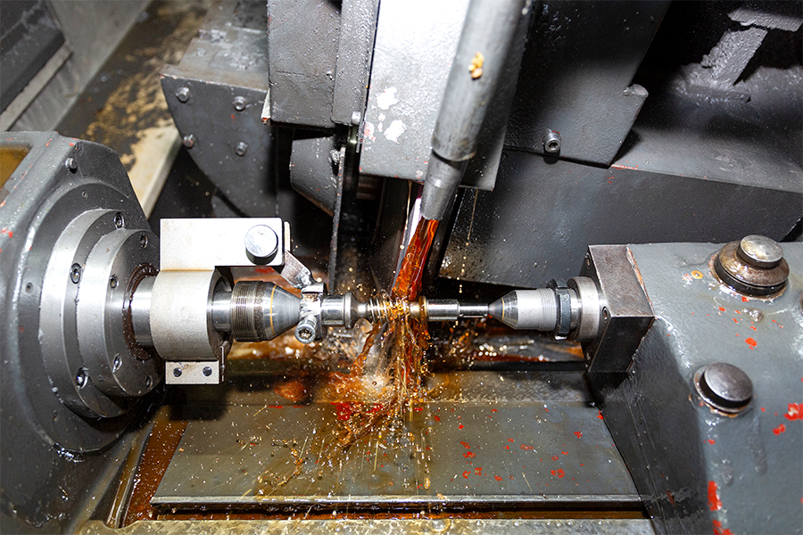
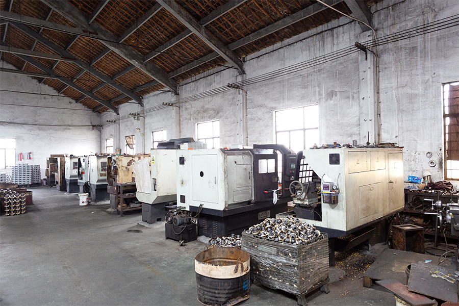
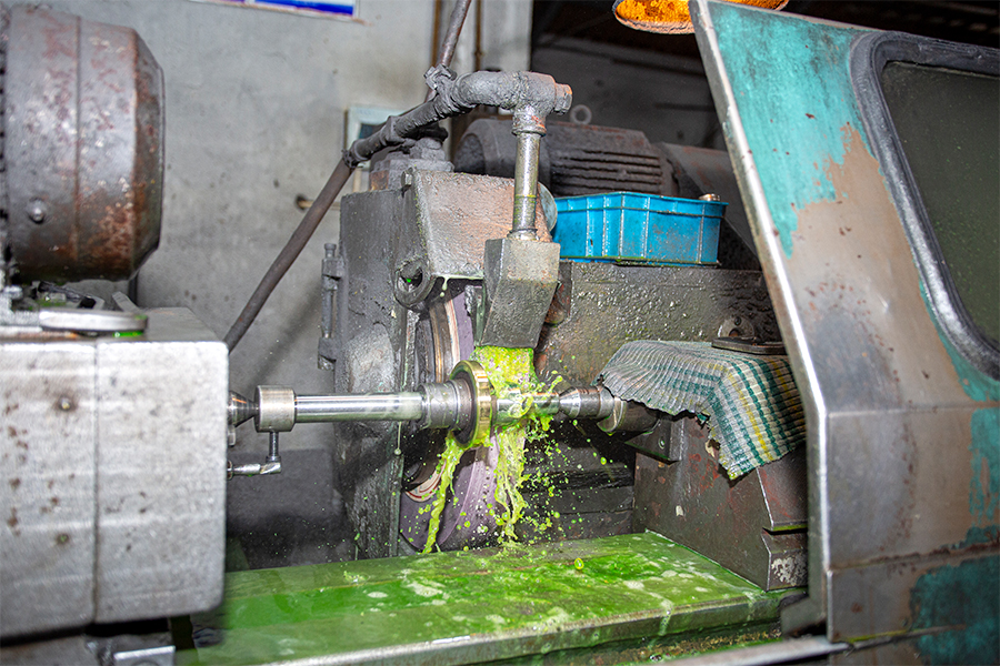
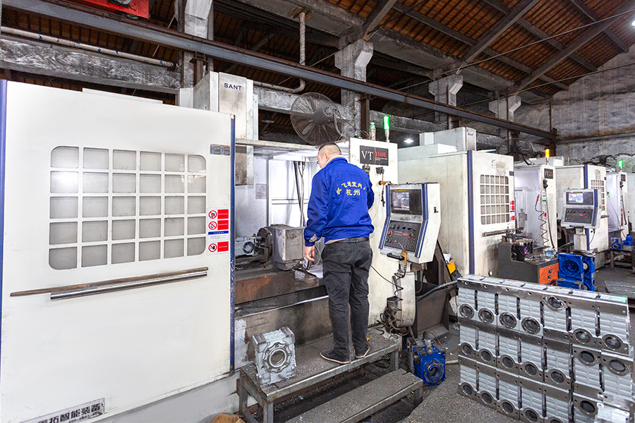
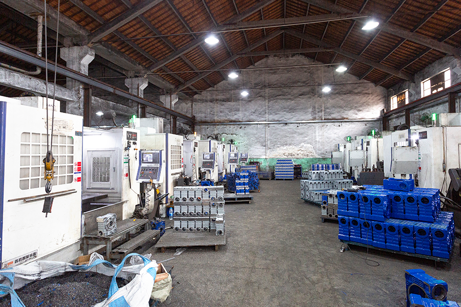
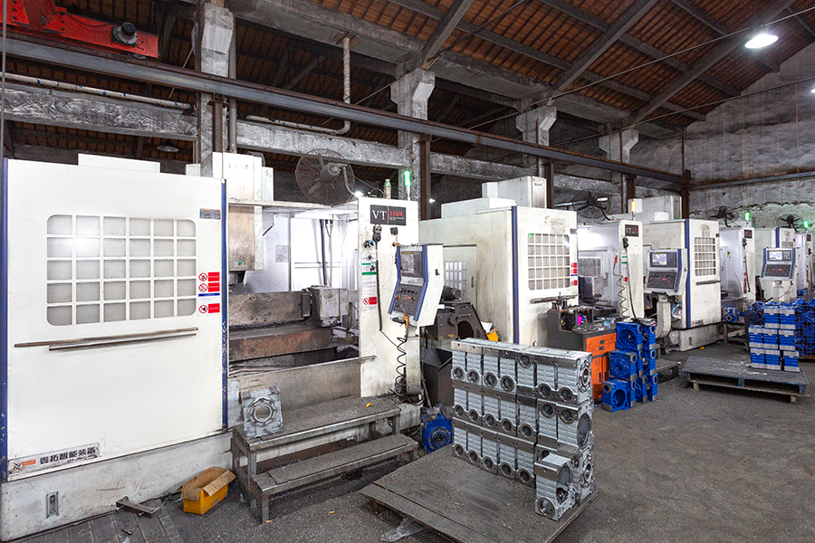
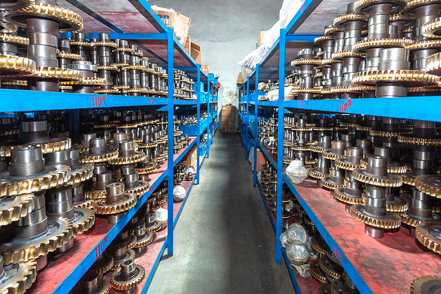
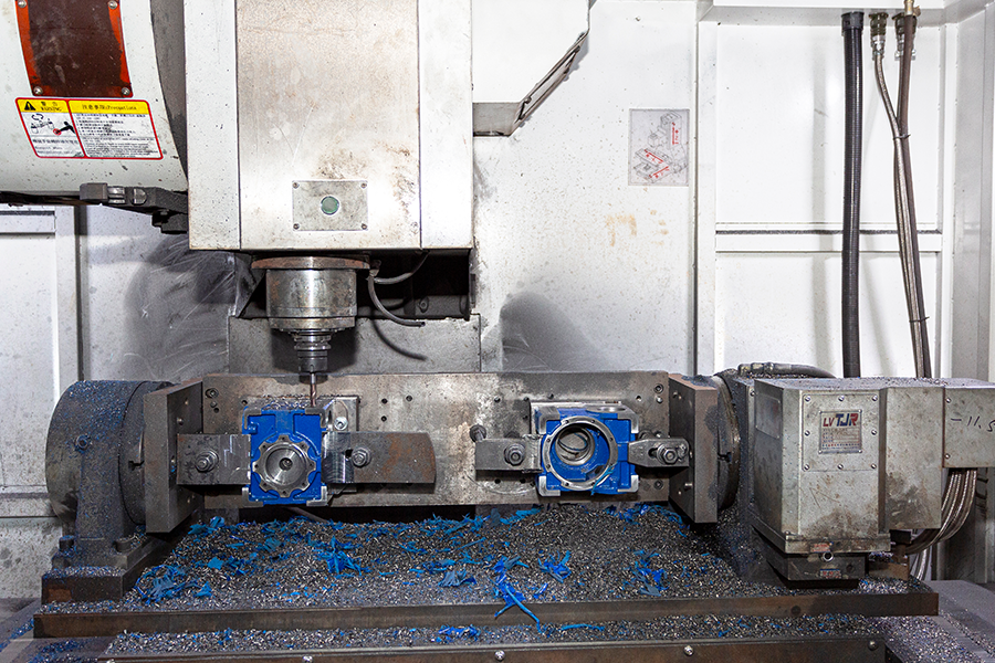
In order to ensure good meshing with the worm wheel, the worm needs to be processed with high precision. Advanced equipment such as CNC gear grinding machines are usually used to grind the worm to ensure the accuracy and surface quality of its helix. High-precision worm processing can reduce the tooth side clearance during the transmission process and improve the transmission accuracy and stability. The manufacturing process of the worm wheel is also very critical. Generally, the worm gear blank is made by casting or forging, and then machined and heat treated. During the machining process, the parameters such as the tooth profile accuracy and pitch error of the worm gear need to be strictly controlled to ensure the precise fit with the worm. Through appropriate heat treatment process, the hardness and wear resistance of the worm gear can be improved and its service life can be extended.
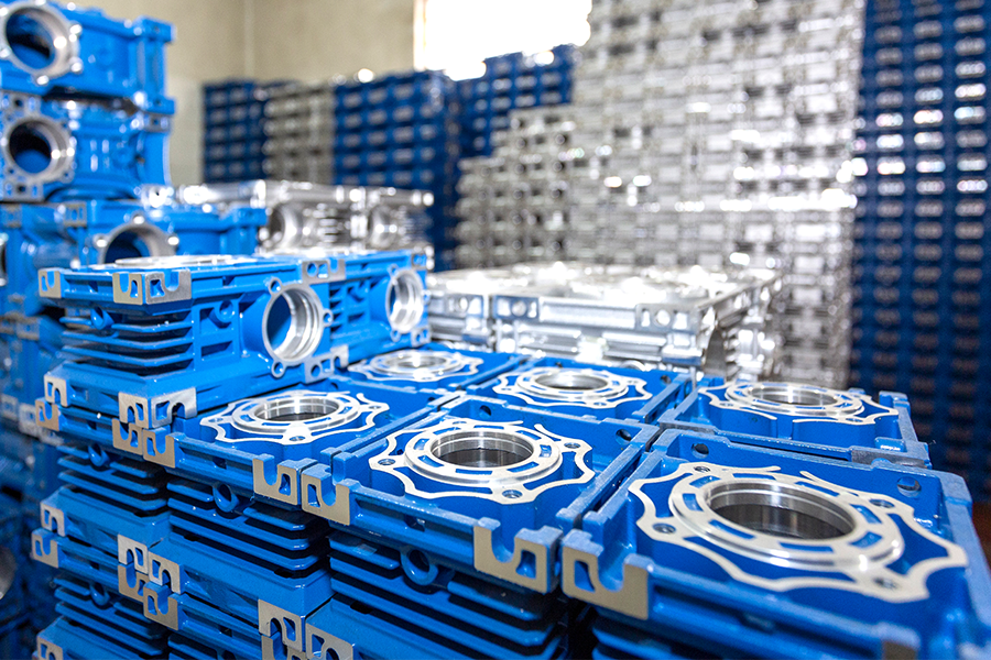
Since the worm gear will generate a certain amount of heat during the transmission process, a good heat dissipation design is required to ensure the normal operation of the reducer. The housing usually adopts a structural design with a large heat dissipation area, such as adding heat dissipation ribs, etc., to improve the heat dissipation efficiency. In some large or high-load worm gear speed reducers, special cooling devices such as fans and cooling water pipes may also be equipped to force heat dissipation to ensure that the temperature of the reducer is always kept within a reasonable range during operation. Reasonable lubrication is essential for the performance and life of the worm gear speed reducer. Common lubrication methods include oil bath lubrication and splash lubrication. In oil bath lubrication, part of the worm gear or worm is immersed in lubricating oil, and the lubricating oil is brought to the meshing part by rotation to achieve lubrication and heat dissipation. Splash lubrication uses the lubricating oil to splash onto various transmission parts when the worm wheel or worm rotates to achieve the purpose of lubrication.
The worm is generally made of alloy steel and undergoes heat treatment processes such as quenching and tempering to improve its hardness and strength. For some special applications, materials such as carburized quenched alloy steel or nitrided steel are also used to further improve the wear resistance and fatigue resistance of the worm. The worm wheel is usually made of bronze, which has good friction reduction and wear resistance, and can effectively reduce the friction coefficient when meshing with the worm, reducing wear and heat. In some light loads or high cost occasions, aluminum alloys or engineering plastics are also used to make worm wheels. The housing materials are mainly cast iron and cast steel. Cast iron has good casting performance and shock absorption performance, and the cost is relatively low, which is suitable for general industrial applications. Cast steel has higher strength and toughness, and is suitable for occasions with large loads and impacts. In some occasions with high weight requirements, lightweight materials such as aluminum alloys are also used to make the housing.
With the continuous advancement of manufacturing technology and material technology, the transmission efficiency of modern worm gear speed reducer has been significantly improved. By optimizing the helical parameters of the worm, adopting high-precision processing technology and reasonable lubrication methods, the transmission efficiency of worm gear speed reducer can reach more than 80%, and in some specially designed reducers, the transmission efficiency can be even higher. Compared with traditional belt drive, chain drive and other methods, worm gear speed reducer has higher transmission efficiency, which can effectively reduce energy loss and reduce operating costs.
Due to the use of high-strength materials and advanced manufacturing processes, worm gear speed reducer has good wear resistance and fatigue resistance. Under normal working conditions, its service life can reach more than 10 years, or even longer. The structure of worm gear speed reducer is relatively simple, with fewer internal transmission parts, which reduces the probability of failure, and maintenance is relatively convenient, further extending its service life. Compared with traditional gear transmission equipment, worm gear speed reducer has obvious advantages in service life.
The meshing transmission mode of worm gear makes the transmission process smoother, with less noise and vibration. Compared with traditional gear transmission equipment, worm gear speed reducer produces lower noise during operation and can provide a quieter atmosphere for the working environment. This has important application value in some occasions with strict noise requirements, such as hospitals, schools, office buildings, etc.
As mentioned above, worm gear speed reducer can achieve high-precision speed control and positioning, and has irreplaceable advantages in some industrial equipment with extremely high motion accuracy requirements. Compared with traditional transmission equipment, worm gear speed reducer can more accurately control the movement speed and position of the equipment and improve the processing accuracy and quality of the product.
The worm gear speed reducer has low energy consumption during operation, which can effectively reduce energy consumption and greenhouse gas emissions. At the same time, due to its long service life, it reduces the frequency of equipment replacement and reduces the generation of waste, which meets the requirements of modern industry for environmental protection. Compared with traditional high-energy consumption and high-pollution transmission equipment, worm gear speed reducer has better environmental performance.
In the automated production line of modern manufacturing, worm gear speed reducers are widely used in various transmission links. On the assembly line of electronic products, the reducer is used to drive the joint movement of the mechanical arm to achieve accurate grasping and assembly of parts; on the welding production line of automobile manufacturing, the reducer provides power for the rotation and movement of the welding robot to ensure the accuracy of the welding position and the stability of the welding quality.
In the automated warehouse, the stacker is a key equipment for automatic storage and retrieval of goods. The worm gear speed reducer is used for the lifting, walking and fork extension mechanisms of the stacker. Through precise speed control and powerful torque output, it ensures that the stacker can quickly and accurately store or remove goods from the shelf. Belt conveyors, chain conveyors, etc. in the logistics conveying system are also inseparable from the support of worm gear speed reducers. The reducer converts the high-speed rotation of the motor into the low-speed, high-torque movement required by the conveyor to achieve smooth transportation of materials. In the sorting system, the reducer is also used to drive the rotating parts of the sorting equipment to accurately sort the goods into different conveying channels.
Crane is a large-scale mechanical equipment commonly used in construction. The worm gear speed reducer plays an important role in the lifting, slewing and luffing mechanisms of the crane. In the lifting mechanism, the reducer transmits the power of the motor to the drum by increasing the torque to achieve safe lifting of heavy objects; in the slewing mechanism, the reducer controls the rotation speed and angle of the crane to ensure that the boom can accurately reach the specified position. Concrete mixers require strong power to drive the mixing blades to rotate to achieve uniform mixing of concrete. The worm gear speed reducer can provide the large torque output required by the mixer to ensure that the mixing blades can operate stably under high loads, and at the same time, through precise speed control, meet the mixing requirements of different concrete mix ratios.
In the filling production line of food and beverages, the worm gear speed reducer is used to drive the turntable, conveyor chain and other components of the filling machine. Through precise speed control, it ensures that the bottle can be accurately positioned under the filling head to achieve precise filling, while ensuring the continuous operation of the production line and improving production efficiency. In the packaging process of food and beverages, worm gear speed reducers are also widely used in equipment such as capping machines and labeling machines. The reducer provides stable power for the transmission parts of these equipment, ensures the accuracy and consistency of the packaging action, and improves the packaging quality.
In some precision surgical instruments, such as electric operating tables and shadowless lamps, worm gear speed reducers are used to achieve precise adjustment and positioning of the equipment. Through high-precision transmission, the operating table can be quickly and smoothly adjusted to the appropriate surgical position, and the shadowless lamp can accurately illuminate the surgical site, providing a guarantee for the smooth progress of the operation. Rehabilitation equipment such as electric wheelchairs and rehabilitation training equipment will also use worm gear speed reducers. The reducer provides stable power for the drive system of these equipment, and meets the different needs of patients during rehabilitation training through precise speed control and torque output.
Before installation, carefully check whether the appearance of the reducer is damaged or deformed, and whether all parts are complete. Check the nameplate parameters of the reducer to ensure that its model and specifications are consistent with the actual use requirements. Clean the mounting base of the reducer and the mounting surface of the equipment connected to it, remove impurities such as oil, dust, rust, etc. on the surface, and ensure that the mounting surface is flat and smooth to ensure the stability of the reducer after installation. According to the installation requirements of the reducer, prepare the corresponding installation tools, such as wrenches, screwdrivers, jacks, lifting equipment, etc., and ensure the integrity and applicability of the tools.
Horizontal installation is the most common installation method and is suitable for most industrial application scenarios. During horizontal installation, the axis of the reducer is parallel to the ground, and the base of the reducer is fixed to the installation base by anchor bolts. During installation, pay attention to adjusting the horizontality of the reducer. You can use a level to measure to ensure that the reducer is in a horizontal state after installation to avoid uneven force on the transmission parts caused by tilting. Vertical installation is suitable for some special equipment layout requirements, such as the need to install the reducer on the top or side of the equipment. During vertical installation, the axis of the reducer is perpendicular to the ground, and the base of the reducer is also fixed to the installation base by anchor bolts. Since the center of gravity of the reducer is high during vertical installation, special attention should be paid to its stability during installation, and support or fixing devices can be added if necessary. Flange installation is to dock the flange of the reducer with the connecting flange of the equipment. This installation method has the advantages of convenient installation and firm connection, and is suitable for some occasions with high requirements for installation space or frequent disassembly. When installing the flange, ensure that the bolt holes of the two flanges are aligned, use appropriate bolts and gaskets for tightening, and tighten according to the specified torque requirements to ensure the reliability of the connection.
Connect the motor to the input shaft of the reducer. Common connection methods include coupling connection and belt drive connection. When connecting the coupling, select the appropriate coupling model and ensure the installation accuracy of the coupling so that the input shaft axes of the motor and the reducer are concentric to reduce vibration and noise during transmission.
The worm gear speed reducer transmits power through the meshing of the worm (active part) and the worm wheel (driven part), and uses the helical teeth of the worm to drive the worm wheel to rotate, achieving the effect of speed reduction and torque increase.
Compact structure, suitable for space-constrained scenarios;
Smooth transmission, low noise;
Can achieve a large transmission ratio;
With self-locking function;
Clear load parameters: calculate load torque, speed, working cycle, and impact coefficient.
Determine the transmission ratio: calculate the required transmission ratio based on the input speed (motor speed) and the target output speed.
Match power and torque: Find a reducer sample and select a model.
Verify installation and environment: Confirm that the installation size, shaft diameter matches the load shaft, and whether the ambient temperature requires special protection.
Evaluate additional functions: If self-locking function is required, confirm the worm lead angle; if high-precision transmission is required, choose a precision reducer.
Choose lubricants with high viscosity index, and synthetic greases can be used in high temperature environments. Observe the oil level through the oil gauge every day to ensure that it is between the upper and lower limits; check after stopping for 30 minutes to avoid oil splashing and misjudgment. Take samples to test the oil quality every month. If emulsification, blackening or metal debris occurs, replace the lubricant immediately. When changing the oil, rinse the box with kerosene to remove deposited impurities; clean the filter once a quarter and replace it when it is seriously blocked.
If the normal operating temperature is exceeded, the machine must be shut down immediately for investigation. The worm bearing position and housing surface temperature can be monitored by an infrared thermometer. The housing amplitude is measured with a vibrometer. Abnormal vibration indicates bearing wear or installation error.
Check the torque of the anchor bolts and end cover bolts every week, and replace the oil seal in time if oil leakage is found. Disassemble and check the wear of the tooth surface every six months. The normal tooth surface should be smooth and free of pitting; if there are grooves or peeling on the tooth surface, the gear pair needs to be ground or replaced.
Maintain good ventilation around the reducer to avoid dust and oil accumulation that affect heat dissipation; use compressed air to blow the heat dissipation ribs of the shell every month. When installing outdoors, install a protective cover to prevent rainwater from invading and causing emulsification of the lubricating oil.
|
Fault phenomenon |
Possible cause |
Solution |
|
Abnormal noise |
1. Insufficient lubrication or grease contamination 2. Poor gear meshing 3. Bearing damage |
1. Add or replace lubricating oil 2. Check axis alignment and grind tooth surface 3. Replace bearings |
|
housing overheating |
1. Add or replace lubricating oil 2. Check axis alignment and grind tooth surface 3. Replace bearings |
1. Reduce the load or add cooling devices 2. Adjust the oil level and replace the lubricant with appropriate viscosity 3. Clean the heat sink ribs and install a fan |
|
oil leakage |
1. Oil seal aging or misplaced installation 2. Sealant failure on the joint surface of the box 3. Clogged vents causing internal pressure to rise |
1. Replace the oil seal and ensure that the lip is not damaged during installation 2. Reapply sealant after disassembly 3. Clean the vent hole to keep it breathable |
|
abnormal output shaft speed |
1. Worm gear wear causes transmission ratio change 2. Motor failure 3. Coupling loose |
1. Check the wear of the tooth surface 2. Check the motor power supply and encoder 3. Tighten the coupling bolts and adjust the coaxiality |
|
abnormal vibration |
1. Bearing clearance is too large 2. Gear meshing impact 3. Foundation installation is not firm |
1. Measure the bearing clearance and replace the bearing 2. Install a buffer device 3. Strengthen the base and adjust the levelness |
The combination of worm and worm wheel can achieve high reduction ratio, which can convert high speed input into low speed output, providing flexibility and adaptability for many industrial applications, and can meet the needs of significantly reduced speed in projects.
The worm has a large diameter, a large number of worm wheel teeth, and a large contact area, which can transmit large torque. It performs well in project applications that need to handle high loads and high torques, and can provide strong power support for equipment.
Compared to other types of reducers, it is more compact, small in size, light in weight, easy to install and carry, and has good applicability for project scenarios with limited space, such as some small mechanical equipment or production lines with narrow installation space.
The special gear structure makes its transmission motion smooth and reduces vibration and noise. For projects with high requirements for running smoothness and noise, such as food processing, medical device manufacturing, etc., it can create a quiet working environment, which is also conducive to the long-term stable operation of equipment.
The worm gear speed reducer can stop and hold the load, prevent the equipment from reversing, improve the safety and reliability of project operation, and is suitable for scenes such as lifting operations and lifting equipment that require fixed position or prevent reversal.
The gear is installed on the output shaft at a 90-degree angle to the input shaft, which can release both ends of the output shaft and provide more engineering design options. At the same time, both solid and hollow output shafts can be used. The hollow output shaft does not require belts or chains to transmit torque, reduces moving parts and maintenance requirements, and can adapt to the installation requirements of different projects.
Compared with some reducers that require multi-stage transmission to achieve the same reduction ratio, the worm gear speed reducer can achieve high reduction in a single stage, reduce the number of gears and bearings, and reduce implementation costs. In addition, its maintenance cost is also low, and its cost-effectiveness advantage is obvious.
1. What is an NRV Worm Gear Reducer? The NRV worm gear speed reducer is a widely used mechanical device...
View MoreIn the stage of modern industrial precision transmission, Worm Gear Machine Screw Lift has become the cor...
View MoreWhat is worm gear speed reducer A worm gear speed reducer is a reduction transmission device composed of ...
View More1. Introduction to Worm Gear Speed Reducers A worm gear speed reducer is a specialized type of gearbox de...
View More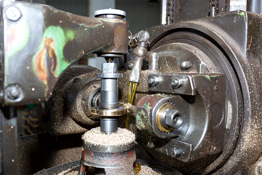
We value your suggestions and questions. If you have any questions about our products and services, please contact us. We will treat you responsibly and reply to your information as soon as possible.

